Aerosol Dip Tube Design: Depletion & Spray Consistency
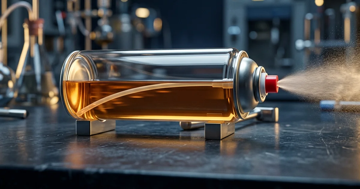
Aerosol dip tube design determines how completely a can empties and how steady its spray stays from the first actuation to the last. The dip tube is the plastic tube that runs from the valve to the bottom of the can, carrying liquid product up to the valve under propellant pressure. Its length, bore, material and end cut control residual product, spray rate and compatibility with the formulation, which is why it deserves deliberate specification and not a catalogue default. This guide explains how a dip tube works, how length and positioning decide product depletion, how bore size and the vapor tap shape spray consistency, how to match tube material to the formula, and how to test a design before scale-up. It extends the pressure and valve fundamentals in our How Aerosol Cans Work guide and sits within the wider aerosol technology and formulations knowledge base.
How an Aerosol Dip Tube Works
In a standard upright aerosol, the valve sits at the top of the can while the liquid product collects at the bottom, so something has to bridge the gap. The dip tube does that job. When the actuator opens the valve, propellant pressure pushes the liquid up the tube, through the valve body and out of the orifices as a spray. Because the tube is the first restriction in the flow path, its design shapes everything that happens downstream of it.
- Dip tube: carries liquid from the base of the can to the valve; its length sets where liquid is drawn from and its bore sets the first flow resistance
- Valve body and stem orifices: meter the flow and begin atomisation as the product leaves the valve
- Actuator: shapes the final spray pattern once the product exits the stem
- Propellant: supplies the pressure that drives liquid up the tube
These parts act as a series of restrictions, so the dip tube cannot be specified in isolation. Reducing the bore of the dip tube, like reducing the body or stem orifice, generally lowers the spray rate and the particle size and can increase the amount of product retained in the can. The tube also connects to the valve body, and the elastomer gasket materials that govern long-term sealing against the formulation are covered in our aerosol valve gasket materials guide.
Not every aerosol uses a dip tube. Bag-on-valve systems hold the product in a sealed, laminated pouch separated from the propellant, which removes the dip tube and allows dispensing in any orientation. That design is explored in our bag-on-valve technology guide and summarised in the Wikipedia aerosol spray overview.
Dip Tube Length and Positioning: Controlling Product Depletion
Dip tube length decides how much liquid is left in the can when spraying stops. A tube that reaches close to the base of the can draws product down to a small residue, while a tube that stops short leaves liquid beneath its inlet that the user can never spray. Length therefore has to be matched to the internal height of the container and the installed height of the valve assembly, because tube, valve and can all vary slightly from part to part. A correctly sized tube allows containers to be substantially emptied despite that manufacturing variation.
| Tube condition | Effect on depletion | Effect on spray |
|---|---|---|
| Too short | Liquid remains beneath the tube inlet, so residual product is higher | Spray can turn gassy while product is still in the can |
| Matched to container height | The inlet reaches the lowest liquid, so residue is minimal | Liquid is drawn consistently until the can is nearly empty |
| Too long | The tip can seat flat against the can base and restrict the inlet | The draw can be reduced or interrupted |
End geometry matters as much as length. Dip tubes are commonly supplied with a straight or an angled cut, and an angled end keeps an entry path for liquid open if the tip meets the base of the can. Tube stiffness also affects positioning, because a flexible tube can curl as it is inserted through the can while a stiffer tube holds a straighter line to the base. Assembly faults of this kind sit alongside the valve and seal failures catalogued in our why aerosol cans leak guide.

Dip tubes of different lengths laid side by side for comparison, the basic variable behind how completely a can empties.
Bore Size, Vapor Taps and Aerosol Spray Consistency
Spray consistency means the last sprays from a can look and feel like the first. Three dip tube features influence it: the internal bore of the tube, the viscosity of the product it has to carry, and the presence of a vapor tap. The bore sets the flow resistance of the first stage of the flow path, so it has to be balanced against the body and stem orifices and not chosen alone.
A vapor tap is a small hole in the dip tube or valve body that lets propellant vapor mix with the liquid on its way to the valve. In the valve patent literature the hole sits in the tube above the liquid entrance and below the initial liquid level, so that once the liquid level falls below it, vapor enters the tube and mixes with the remaining liquid, substantially re-establishing the spray characteristics that would otherwise deteriorate late in the can's life. The hole is smaller than both the exit orifice and the bore of the tube, and the ratio of these cross-sectional areas is critical to how well it works.
| Design feature | What it changes | Design consideration |
|---|---|---|
| Dip tube bore | Sets first-stage flow resistance; a smaller bore generally lowers spray rate and particle size and can increase retained product | Balance against the body and stem orifices; never size it alone |
| Product viscosity | A more viscous product meets higher resistance in a narrow tube | The flow path must not choke the draw of a thick formulation |
| Vapor tap hole | Lets propellant vapor mix with liquid, restoring spray characteristics once the level falls below the hole | Smaller than the exit orifice and the tube bore; the area ratio is critical |
| Valve architecture | Changes the downstream path the liquid takes after the tube | Review alongside tilt valve versus vertical valve selection |
The effect of bore on flow follows the same fluid mechanics that govern flow through any narrow tube: resistance rises as the bore narrows and as the fluid becomes more viscous, as described by the Hagen–Poiseuille equation. For a dip tube this means a thick formulation and a narrow bore compound each other, and the combination shows up as a weak or uneven spray.
Dip Tube Material and Chemical Compatibility
Dip tubes are commonly extruded from polyethylene in LDPE, MDPE or HDPE grades, or from polypropylene, and the choice is driven by compatibility with the formulation. The tube sits in constant contact with solvents, actives and liquefied propellant for the full shelf life, so a mismatch shows up as swelling, softening, stiffening or cracking. Patent literature on dip tubes notes that environmental-stress-cracking-resistant grades of polypropylene or HDPE matter where the product is prone to causing that failure, and that the resistance is unnecessary where no such substance is present.
| Material | Character | Compatibility consideration |
|---|---|---|
| Polyethylene (LDPE, MDPE, HDPE) | Flexible and widely extruded for dip tubes; stiffness rises from low- to high-density grades | Confirm resistance to the formulation's solvents, since solvent absorption can soften or swell polyolefin tubing |
| Polypropylene | Stiffer than low-density polyethylene and widely used for dip tubes | Stress-cracking-resistant grades matter where the product is prone to inducing that failure |
Compatibility is confirmed by storage testing of the complete assembly, meaning can, valve, gasket, dip tube and formulation together, and not from material data sheets alone. It is the same principle behind the elastomer testing covered in our valve gasket compatibility guide, and it matters most for solvent-rich products that sit in contact with the tube for months.

Valve assemblies with attached dip tubes beside a glass cutaway can with the liquid level visible, the assembly that controls draw from the base of the can.
Testing an Aerosol Dip Tube Design Before Scale-Up
A dip tube specification is only proven when filled cans behave the same way from first spray to last. Testing therefore follows the product through its whole life instead of checking a single spray. The core measures are delivery rate, residual product at end of life and spray quality across the can's contents. ASTM D3069, which ASTM now classes as a historical standard for delivery rate of aerosol products, states that delivery-rate tests help evaluate one aspect of valve performance and are a prerequisite to storage testing.
- Fill representative cans with the final formulation and propellant, using production-grade dip tubes, valves and cans
- Measure delivery rate at the start, middle and end of the can's life to confirm that the draw stays steady
- Spray to exhaustion and weigh the residual product to quantify depletion
- Inspect spray quality across the can's life, noting any gassy or spitting discharge near the end
- Store the filled cans and repeat the tests, so swelling, softening or stress cracking of the tube is caught before launch
- Repeat on production-line cans, because tube length and seating differ between hand-built laboratory cans and line-filled units
Results from this testing belong in the technical file that supports scale-up, alongside the process controls described in our From Lab to Factory guide. Industry bodies such as BAMA publish technical guidance for aerosol manufacturers that can help frame acceptance criteria for delivery rate and residual product.
Troubleshooting Dip Tube Problems and Design Fixes
Dip tube problems show up as a small set of symptoms, and each one points to a specific design variable to check first. Working from symptom to variable shortens troubleshooting and avoids reformulating a product whose real fault is mechanical. The table below maps the most common symptoms to the first variable worth examining.
| Symptom | First design variable to check |
|---|---|
| Product left in a can that has stopped spraying | Tube length against container height, and the end cut |
| Spray turns gassy or spits late in the can's life | Presence and sizing of a vapor tap, and the tube bore |
| Spray rate lower than target | Tube bore against the body and stem orifices; reducing the bore lowers spray rate |
| Tube softens, swells or cracks in storage | Tube material grade against the formulation, including stress-cracking-resistant grades |
| Weak or no draw on the first actuations | Tube fit and seating at the valve body connection |
When a product genuinely has to spray from any angle, the fix is architectural and not a longer tube. A bag-on-valve system removes the dip tube altogether, and the trade-offs against a conventional dip-tube can are covered in our bag-on-valve technology guide. For a conventional can, the design discipline is the one running through this guide: specify length from real geometry, balance bore against the valve path, choose material from storage data, and prove the result on production cans.
Frequently Asked Questions
What does an aerosol dip tube do?
How long should an aerosol dip tube be?
Why does an aerosol spray gassy or spit near the end of the can?
What materials are aerosol dip tubes made from?
Does dip tube diameter affect spray rate?
Do all aerosol cans use a dip tube?
How is dip tube performance tested?
Need Expert Aerosol Consulting?
Our team provides end-to-end aerosol technical consultancy — from formulation development and propellant selection to filling line setup, regulatory compliance, and market launch strategy.
Get a Free Consultation